
Brass Valve Installation Pitfalls: Leaks and Thread Damage
Installation Field Guide
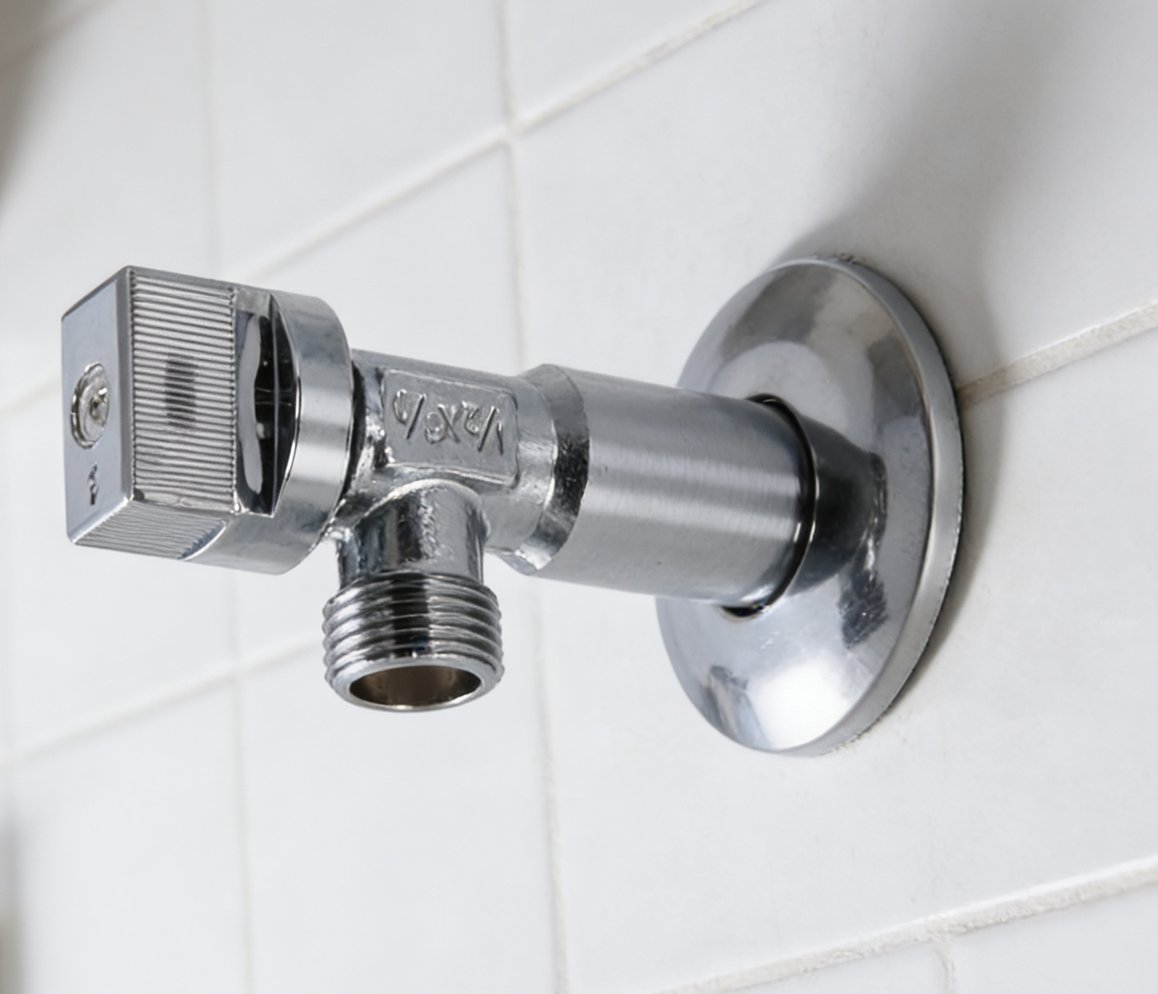
Three weeks after handover of a twelve-unit apartment fit-out, the maintenance log shows the same three entries that appear on almost every residential plumbing project: a weep at a lavatory angle stop, a slow drip from the stem of a laundry supply stop, and a split thread on a water-heater ball valve. All three valves were installed on lines running 40 to 80 psi in dry to high-humidity indoor conditions, well inside any of their published ratings.
None of those failures was a material failure. Each one was decided before the handle was ever turned: the wrong thread system for the outlet, a seal design that did not match the duty of the line, or mechanical damage created during make-up. Understanding how connection leaks, stem leaks and thread damage happen is what separates a valve that survives a decade of quarter-turn operation from one that generates a callback in month two.
Defining the Three Failure Modes Precisely
Before choosing a valve, it helps to separate the failure modes, because each one has a different root cause and a different design answer.
1. Connection leakage
A connection leak appears at the joint between the valve body and the pipe: the threaded inlet, the compression outlet, the PEX or press end, or the supply hose connection. It is a sealing failure at the interface, and it is usually created by one of four conditions: a mismatched thread form between valve and pipe, insufficient or excessive thread engagement, a missing or displaced sealing washer on a parallel-thread joint, or pipe strain that pulls the joint open after tightening.
2. Stem leakage
A stem leak shows as water at the handle or under the packing nut. The stem passes through the body, so it needs its own seal: an O-ring set, a PTFE gland, or a compression packing. Repeated quarter-turn operation wears that seal if it is undersized, if the stem surface is scored, or if debris reaches the seal area. A weep at the stem on a brand-new valve almost always indicates damage during assembly or a seal design that is too light for frequent operation.
3. Thread damage
Thread damage covers cross-threading, stretched or cracked threads from over-torque, and thread damage caused by holding the valve body with the wrong tool. Brass is softer than steel, so a steel wrench jaw applied directly to a brass thread or a brass body can deform it. Once a thread is deformed, the joint will either leak immediately or fail on the next service.
4. Deterioration over time
The fourth mode is slower and easier to miss: seal aging, dezincification in aggressive water, and sediment build-up on seats and screens. A valve that passed its commissioning test can still fail two or three years later if the alloy or the seal compound is not suited to the water chemistry and the operating temperature of the line.
The practical rule: connection leaks are prevented by thread discipline, stem leaks by seal and stem design, and thread damage by installation technique. No single product feature covers all three, which is why valve selection and installation practice have to be planned together.
Why Residential Water Lines Punish Small Errors
Fixture supply lines in bathrooms, kitchens and laundry rooms typically run at 40 to 80 psi (0.28 to 0.55 MPa) with water temperatures from 4°C to 60°C, in environments that range from dry to high humidity, behind fixtures where space is limited and access is awkward. PEX branch lines in whole-house repiping carry working pressure up to 100 psi (0.7 MPa) and water temperature up to 180°F (82°C). Angle valve installations in wet and humid locations are commonly rated for a working range of 40 to 150 psi (0.28 to 1.0 MPa) and 4°C to 90°C.
Those numbers are modest, which is exactly why installation errors dominate the failure record. There is no pressure margin driving the failure; the failure is already built into the joint.
Two regulatory shifts have made thread and material discipline more important rather than less. Under NSF/ANSI 372 and the US Safe Drinking Water Act, wetted surfaces in potable water contact are limited to a lead content of 0.25% or less, and materials in contact with drinking water must meet NSF/ANSI 61 health-effect requirements. For USA and Canada, brass components for these applications are specified with lead-free brass, NSF 61 and NSF 372 certification, cUPC listing, and compliance with ASME A112.18.1 / CSA B125.1; for other markets, BSP threads and 100% pressure testing are the corresponding requirements. Threads on North American potable water connections are specified to ASME B1.20.1 (NPT), while ISO 228-1 covers the parallel BSP thread family, where the thread itself is not the pressure-tight element.
The market context explains why so much of this hardware is sourced internationally: the global brass valves market was valued at USD 14.8 billion in 2025 and is projected to reach USD 24.1 billion by 2034, according to Dataintelo, with Asia Pacific holding a 41.2% revenue share in 2025 and North America approximately 26.1%. More suppliers, more thread systems and more alloy options in the same project make connection discipline the single highest-value skill on site.
Design Features That Address Each Failure Mode
LONGDA BRASS VALVE is the brass valve brand of Zhejiang Longda Technology Co., Ltd., a manufacturer established in 1993 in the Xuanguang Industrial Zone, Lupu Town, Yuhuan County, Zhejiang Province, China, producing brass valves and brass fittings for residential and commercial water, heating and gas systems. The design points below follow the published product data for its valve families, and each one maps to a specific failure mode described above.
Hot-forged bodies instead of cast bodies
Forging eliminates the internal voids that can remain in castings, and it removes the need for secondary zinc plating that can later peel and contaminate water. The ball valve range uses hot-forged normal brass or lead-free brass bodies, and the brass fittings range uses hot-forged CW617N, Hpb59 or C37700 with a dezincification-resistant option. Where a cast route is used elsewhere in the industry, ASTM B584 specifies the chemical and mechanical requirements for copper alloy sand castings, which is a useful reference point when comparing a forged and a cast body on the same drawing.
Seats and seals matched to the duty
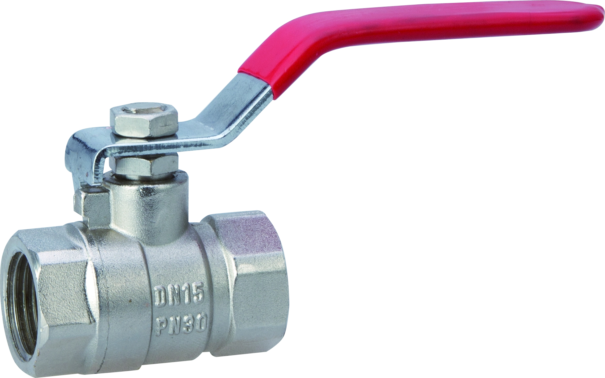
Sealing is where the difference between a two-year valve and a ten-year valve is decided. PTFE seats are used across the ball valve, angle valve and supply stop ranges because they are self-lubricating and resist adhesion to the ball. O-rings are specified in NBR or FKM depending on temperature and media. The supply stop range uses self-lubricating PTFE seats with a double O-ring arrangement for added safety, and the ART.60621 brass water ball valve uses two internal PTFE seats for internal leaktightness plus an external PTFE sealing gland for stem leaktightness — a two-level seal rather than a single barrier.
The gate valve takes a deliberately different route: a brass-to-brass metal seat with no rubber seal in the flow path, which removes elastomer aging from the equation entirely and suits infrequent shut-off duty.
Stem design and blow-out protection
The ball valve range uses a blow-out-proof stem design, so the stem cannot be ejected from the body under pressure even if the retaining arrangement is disturbed. Stem material is matched to the family: chrome-plated brass balls with brass stems on the standard ball valve, and either a brass or a POM stem on the ART.98011 angle valve, where the quarter-turn POM option reduces operating torque at the handle. The gate valve uses a rising stem with PTFE or EPDM packing, and its test pressures are specified at 1.5 times rated pressure for the shell and 1.1 times rated pressure for the seat.
Thread systems that match the market
NPT and BSP are both produced across the ball valve, gate valve, check valve, Y strainer and fitting ranges, which lets a project hold one thread standard per line instead of mixing them. This matters because NPT and BSP are not interchangeable. NPT is a tapered thread intended to seal at the thread engagement; BSP parallel threads per ISO 228-1 are not pressure-tight on the thread itself, so the joint depends on a sealing washer or gasket at the mating face. A parallel-thread valve threaded into a tapered-thread outlet will either bottom out before sealing or crack the body.
Filtration upstream of the critical valves
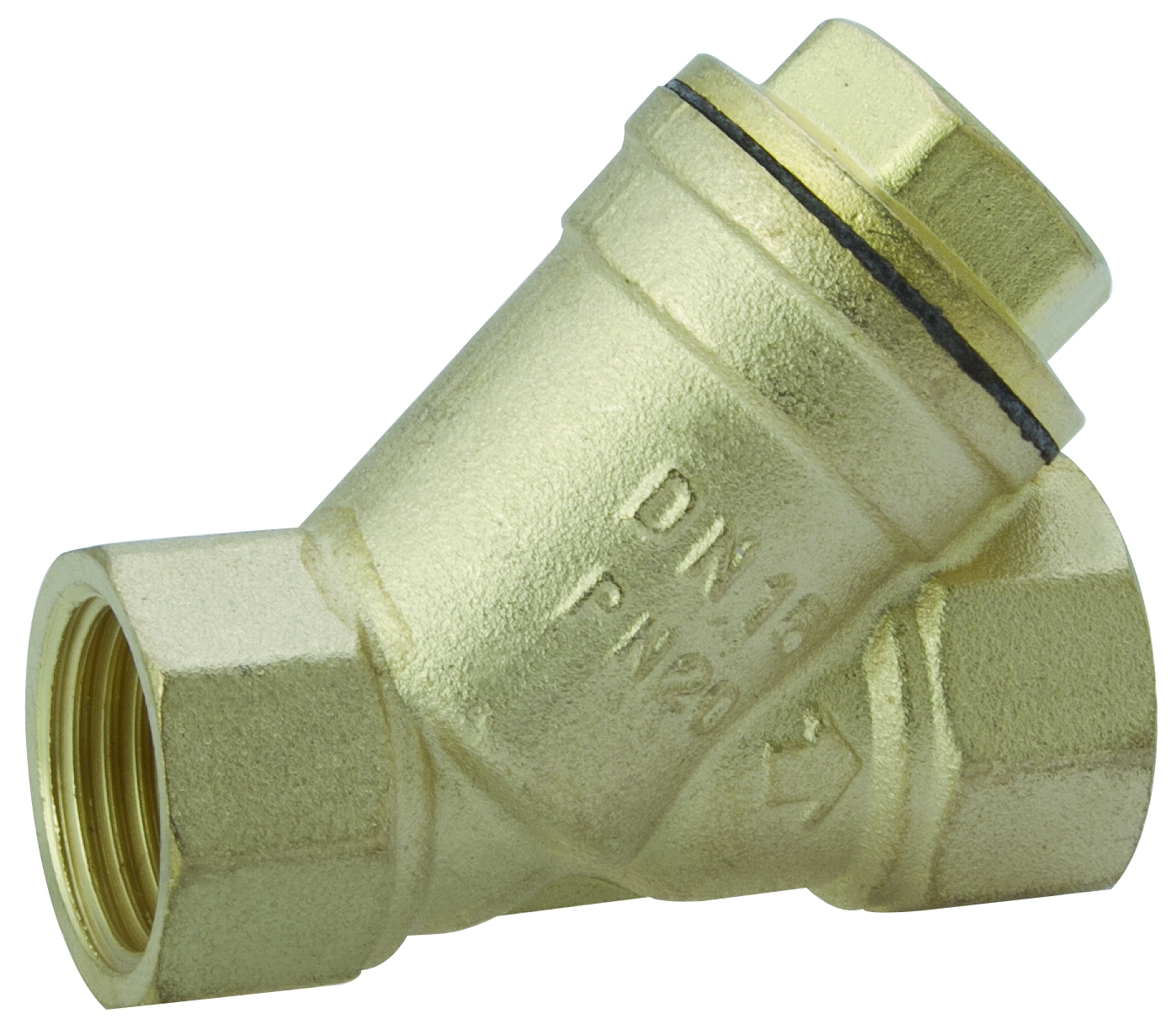
Debris is the most common external cause of both seat leakage and stem damage. The Y strainer range uses an SS304 stainless steel screen in 20, 40, 60 or 80 mesh, a one-piece hot-forged brass body rated 200 WOG, and a blow-down drain plug that allows in-line flushing without disassembly; the screen itself is replaceable without removing the valve or breaking the pipeline. Placing a strainer ahead of meters, pressure reducing valves, pumps and ball valve seats protects the downstream components that are expensive to replace.
Step-by-Step: Eight Checks From Unboxing to Handover
Step 1 — Match the valve family to the line, not to the shelf
A fixture stop is not a shut-off valve and a check valve is not a strainer. Use a quarter-turn supply stop or angle valve for local fixture isolation, a full-port ball valve for branch or whole-house shut-off, a gate valve where infrequent isolation with minimal pressure loss is required, a check valve where backflow must be stopped, and a Y strainer where debris has to be captured. The angle valve and supply stop families are rated at 125 psi and cover 1/2" × 3/8" and 1/2" × 1/2" fixture connections.
Step 2 — Confirm the thread standard before the first turn
Identify whether the outlet is NPT or BSP, and whether the thread is tapered or parallel. NPT is specified to ASME B1.20.1; BSP parallel threads fall under ISO 228-1 and require a face seal. Do not attempt to convert one to the other with extra sealant or extra torque — that is how deformed threads and split bodies are created.
Step 3 — Inspect the body and threads on arrival
Check the thread crests for flat spots or burrs, confirm the body has no visible porosity or plating damage, and verify the stem turns freely through its full quarter turn before installation. A stem that is stiff out of the box will usually leak after commissioning.
Step 4 — Prepare the pipe end
Cut square, deburr both inside and outside, and blow the line clear. Metal chips left in the pipe are the most common cause of a scored ball or a damaged seat found at first operation.
Step 5 — Apply sealant to the right element
On tapered NPT joints, apply thread sealant to the male thread, leaving the first two crests clean so no excess enters the flow path. On parallel BSP joints, seal at the face with the correct washer rather than relying on the thread. Excess sealant that enters the body can block a seat or jam a check valve disc.
Step 6 — Hand-tighten first, then wrench on the body
Thread by hand until the joint is snug, then finish with a wrench applied to the valve body or the designated flats — never to the handle or the stem. Holding a brass valve by the lever transfers torque through the stem and is a direct cause of stem seal damage.
Step 7 — Support the pipe and remove strain
Pipe strain is a silent connection leak. If the valve has to be pulled into alignment, the joint will be pre-loaded and will weep once the system reaches operating temperature. Support the pipe on both sides so the valve body carries no bending load.
Step 8 — Pressure test, then operate the valve
Test the joint at system pressure and observe both the connection and the stem area. Then operate the valve through a full open-close cycle and re-check. A valve that is installed but never cycled before handover is an untested valve, and the first operation will happen in front of the building owner.

Where These Pitfalls Appear: Four Project Scenarios
Bathroom lavatory and toilet connections
Behind-fixture installations combine limited space, high humidity and frequent operation. A 90° angle valve redirects flow from the wall outlet to the fixture hose with local shut-off, allowing maintenance without cutting the building supply. The failure pattern here is almost always a stem weep caused by holding the valve by the handle during tightening, or a connection leak caused by a missing face washer on a parallel thread.
Kitchen and laundry supply points
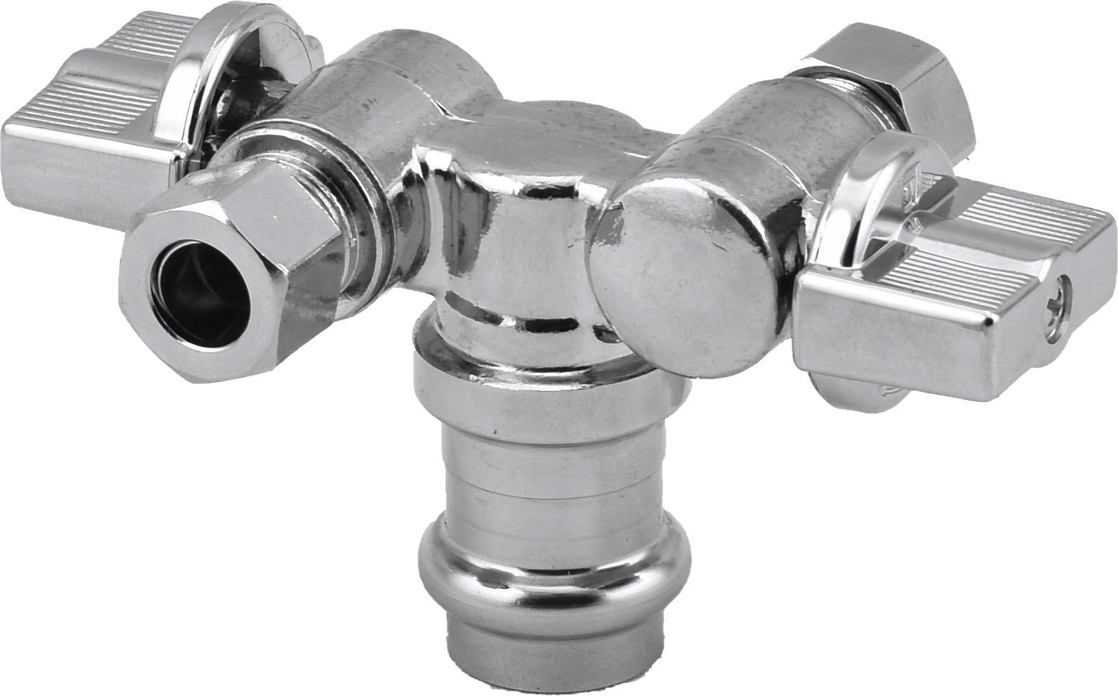
Dishwasher, ice-maker and washing machine lines are fast-cycling and, in the case of washing machines, subject to water hammer. Supply stops with a water hammer arrestor are available for exactly this duty, and quarter-turn operation reduces the torque applied to the stem over the life of the valve. Straight and angle versions are both available, with compression, FIP, PEX, sweat and threaded connections.
Whole-house repiping and branch isolation
On PEX-A systems, ball valves with ASTM F1960 cold expansion connections form a permanent joint without reducing the pipe inner diameter; full-port shut-off keeps pressure drop minimal across the branch. The installation pitfall here is mixing connection systems on one manifold, which multiplies the number of joint types a technician has to get right.
Heating, plant rooms and protected equipment
In heating and chilled water circuits, check valves prevent backflow through pumps, and Y strainers protect meters, pressure reducing valves and pump impellers. Swing check valves and spring-loaded in-line check valves are both available, and installation orientation matters: the correct body type must be selected for horizontal or vertical pipe runs, as stated in the product data.
Valve Family Comparison for Residential and Light Commercial Lines
| Valve family and model | Size range | Pressure rating | Temperature | Sealing and seat design | Connection | Installation risk to control |
|---|---|---|---|---|---|---|
| Brass Ball Valve 8081 | 1/2"–4" (DN15–DN100) | 600 WOG (4.1 MPa) | -20°C to 150°C | Chrome-plated brass ball, PTFE seats, NBR / FKM O-rings, blow-out-proof stem | Female NPT or BSP; also press, PEX, compression, SWT, push-fit | Over-torque through the lever; debris scoring the ball |
| Brass Gate Valve T-22017A | 1/2"–4" (DN15–DN100) | 200 WOG (1.4 MPa) | -20°C to 120°C | Brass-to-brass metal seat, rising stem, PTFE / EPDM packing | Female NPT or BSP | Using it for throttling instead of full open or closed |
| Brass Check Valve LD 30303 | 1/2"–2" (DN15–DN50) | 200 WOG (1.4 MPa) | -20°C to 150°C | Brass disc with PTFE sealing face, SS304 spring, NBR / EPDM O-ring | Female NPT or BSP; also press, PEX, MPT, SWT | Wrong orientation for horizontal or vertical pipe runs |
| Brass Angle Valve ART.98011 | 1/2" × 1/2" and 1/2" × 3/8" (DN15) | 125 psi WSP / 600 WOG | 0°C to 90°C | Quarter-turn brass ball or POM stem, PTFE / NBR seats | Hot-forged brass body, threaded | Holding the handle during tightening; sealant entering the seat |
| Brass Supply Stop 98023-LF | 1/2" × 3/8" and 1/2" × 1/2" | 125 psi | -20°C to 120°C | PTFE seats, double O-ring sealing, quarter-turn or multi-turn | Compression, FIP, PEX (ASTM F1960), sweat, threaded | Misaligned compression nut; mixed connection types on one manifold |
| Brass Y Strainer LD.73154 | 1/2"–2" (DN15–DN50) | 200 WOG (1.4 MPa) | -20°C to 150°C | SS304 screen 20/40/60/80 mesh, NBR / EPDM gasket, replaceable screen | Female NPT or BSP; press and solder options | No access for the blow-down plug; mesh too coarse for the debris present |
| Brass Fittings 15111 | 1/4"–2" (DN8–DN50) | Up to 600 WOG (4.1 MPa) | -20°C to 150°C | Hot-forged brass body, DZR option, lead-free compliant for potable water | NPT or BSP; threaded, sweat, PEX, PEX-A, press, push-fit | Mixing thread standards and connection systems in one assembly |
Comparison based on published product data for the LONGDA BRASS VALVE families listed. Ratings apply to the valve itself and must be checked against the pressure and temperature of the line it serves.
Troubleshooting Matrix: Symptom to Corrective Action
| Symptom | Most likely cause | Corrective action |
|---|---|---|
| Drip at the inlet or outlet joint at commissioning | Thread form mismatch, missing face washer on a parallel thread, or insufficient engagement | Isolate the line, disassemble, clean the thread, re-seal on the correct element, re-tighten on the body flats |
| Weep at the stem or under the packing nut | Seal damaged during assembly, scored stem, or seal design too light for frequent operation | Replace the valve; specify a blow-out-proof stem, PTFE gland or double O-ring design for high-cycle points |
| Cracked or deformed thread on a new valve | Cross-threading or over-torque, often with a wrench on the handle | Replace the valve; hand-thread first, use a thread gauge on receipt, wrench on the body only |
| Reduced flow at the fixture | Debris on the seat or a blocked strainer screen | Flush the line, clean the screen through the blow-down plug, replace the screen element without removing the valve |
| Check valve chatter or failure to close | Wrong body type for the pipe orientation, or debris on the disc | Match swing or spring-loaded type to horizontal or vertical installation; clean or replace the disc |
| Leak appearing after two or three seasons | Elastomer aging, dezincification in aggressive water, sediment build-up | Specify DZR brass and the correct O-ring compound, and add upstream filtration |
Field diagnosis should always be confirmed against the actual product datasheet and the system pressure test record.
What 100% Factory Testing Actually Covers
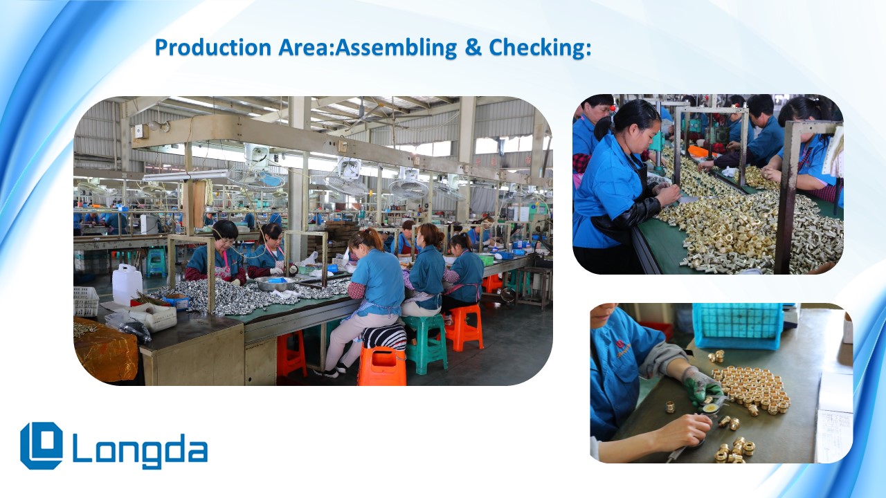
Testing is the part of the specification that buyers cannot see in a photograph, so it needs to be described in concrete terms. At Zhejiang Longda Technology Co., Ltd., production runs 100% air pressure tested under water before shipment, thread gauges are checked on every lot, and a lead-free material test report is available for potable water orders. The published after-sales position is technical support and installation guidance, a 12-month quality warranty, and free replacement for quality defects.
The manufacturing base behind those commitments covers more than 30,000 m², with about 200 employees, an annual output of 7,500 tons and more than 360 sets of processing and testing equipment, including spectral analysis instruments, roundness measuring equipment, salt-spray test boxes and high-pressure testing sets. Products are IAPMO and ALS certified, and around 95% of output is exported to the EU, USA, Canada and South America.
Field evidence for supply stop quality is easier to check at volume than at sample stage. A US manufacturer and a Canadian distributor, both supplying bathroom and kitchen fixture shut-off valves for residential plumbing, have run this product family for three years at 8,000,000 pcs per year and 70,000,000 pcs respectively, with zero leakage complaints and a 100% pass rate in retail quality audit, and repeat orders every month. The contributing factors were cUPC and NSF 61 certification, chrome-plated corrosion resistance, quarter-turn operation, retail packaging and lead-free brass suitable for potable water.
Frequently Asked Questions
What certifications does a brass angle valve need for residential plumbing in the USA and Canada?
For USA and Canada, the application requires lead-free brass with a wetted surface lead content of 0.25% or less, NSF/ANSI 61 and NSF/ANSI 372 certification, cUPC certification, and compliance with ASME A112.18.1 / CSA B125.1. NPT threads are specified to ASME B1.20.1, and 100% pressure testing is part of the requirement. For markets outside the USA and Canada, BSP threads and 100% pressure testing are the corresponding requirements. Buyers should also confirm that the material test report is supplied with the shipment, not only at quotation stage.
Can a brass angle valve manufacturer customize the valve for a residential plumbing project?
Yes. Customization for this product family covers size in the 1/2"–3/4" range, connection type (FIP × compression, IPS × compression, FIP × FIP, PEX × PEX, PEX × compression, press × compression, EXP × compression, EXP × EXP, EXP × press and similar combinations), handle type including quarter-turn lever or multi-turn handle, chrome finish, logo, packaging in blister or box, and certification support for cUPC and NSF. Monthly capacity for this family is 500,000 pcs, which is the relevant number when a project schedule overlaps with a distributor's replenishment cycle.
What MOQ and lead time should a distributor plan for on a brass angle valve program?
The published minimum order quantity for this family is 1,000 pcs per size, with a lead time of 30 to 60 days depending on configuration and order volume. Sample lead time is 5 to 7 days. For broader brass valve programs the lead time runs from roughly 20 to 50 days depending on product type, and MOQ varies by size, so a mixed container should be planned size by size rather than quoted as a single figure.
How should a buyer validate brass valve samples before releasing a production order?
Validate at three levels. First, structure: confirm PTFE seats, double O-ring sealing on the supply stop, quarter-turn ball core design and chrome-plated anti-corrosion finish against the drawing. Second, evidence: require the 100% air pressure test record under water, the thread gauge inspection result for the lot, and the lead-free material test report. Third, terms: confirm the 12-month quality warranty and the free replacement policy for quality defects, plus the installation guidance offered for site teams. A sample that passes a visual check but has no test documentation has only been inspected, not validated.
How do installation teams avoid callbacks after handover?
Callback prevention is a sequence rather than a single step: confirm the thread standard before the first turn, hand-tighten before wrenching, apply torque to the body flats rather than the handle, support the pipe to remove strain, then pressure test the joint and cycle the valve before handover. Where a valve has to be replaced after a leak, the replacement should carry the same design features — a blow-out-proof stem, PTFE seats and a sealing arrangement rated for the line. Contractors and distributors who want to check a specific configuration against a bathroom, kitchen or laundry installation can request a sample set or the LONGDA Global catalogue at the catalogue download page, or send the line details to sales@ld-valve.com for a technical review.
Conclusion
Connection leaks, stem leaks and thread damage are not random. Each one has a predictable cause: the wrong thread system for the outlet, a seal design that does not match how often the valve is operated, or mechanical damage created during make-up. Matching the valve family to the line, confirming NPT or BSP before installation, and checking hot-forged bodies, PTFE seats, NBR or FKM O-rings and blow-out-proof stem designs where they apply will remove most of that risk before the first wrench is picked up.
LONGDA BRASS VALVE supplies gate, check, ball, angle stop, supply stop, Y strainer and brass fitting families from a single production base in Yuhuan, Zhejiang Province, China, with NPT and BSP thread systems, lead-free options certified to NSF/ANSI 61 and NSF/ANSI 372, cUPC listings where applicable, and 100% factory testing on every unit. Zhejiang Longda Technology Co., Ltd. can be contacted at sales@ld-valve.com or +86 13506869135, and the full range is documented at www.ld-valve.com.
Check the Valve Before the Callback
Send us the line details — medium, pressure, temperature, thread standard and connection type — and we will confirm the matching brass valve family, the correct seal configuration and the certification documents required for your market. Sample sets are available in 5 to 7 days.
Download the LONGDA Global catalogue | Request a sample via WhatsApp | sales@ld-valve.com
Have Questions or Need More Details?
Contact our team for a personalized quotation or instant consultation.
Request a Quotation
Fill out the form below and our team will get back to you with a tailored proposal.
WhatsApp Direct Chat
Prefer to chat in real-time? Message us on WhatsApp for instant assistance & quick answers.
- Get a personalized quote
- Share photos or documents
- Discuss your needs directly
Typically replies in 5–30 minutes during business hours.