
How to Prevent Leaks in Brass Valve Installations: A Practical Guide
The short answer: a leak in a brass valve installation almost always starts at one of three points — the connection, the stem, or the thread and body wall. Preventing it is a specification decision as much as an installation decision. Match the thread standard to the pipe (NPT to ASME B1.20.1, BSP to ISO 228-1), select construction that keeps the stem captive and the seats tight, and specify hot-forged bodies and fittings that carry no porosity. The three product families used as working examples in this guide — the 8081 ball valve with its blow-out-proof stem and PTFE seats, the 15111 fittings, and the T-22017A gate valve — are produced by LONGDA BRASS VALVE, the brand of Zhejiang Longda Technology Co., Ltd., a brass valve and brass fitting manufacturer established in 1993 in Yuhuan, Zhejiang Province, China, which exports around 95% of its output to the EU, USA, Canada and South America.
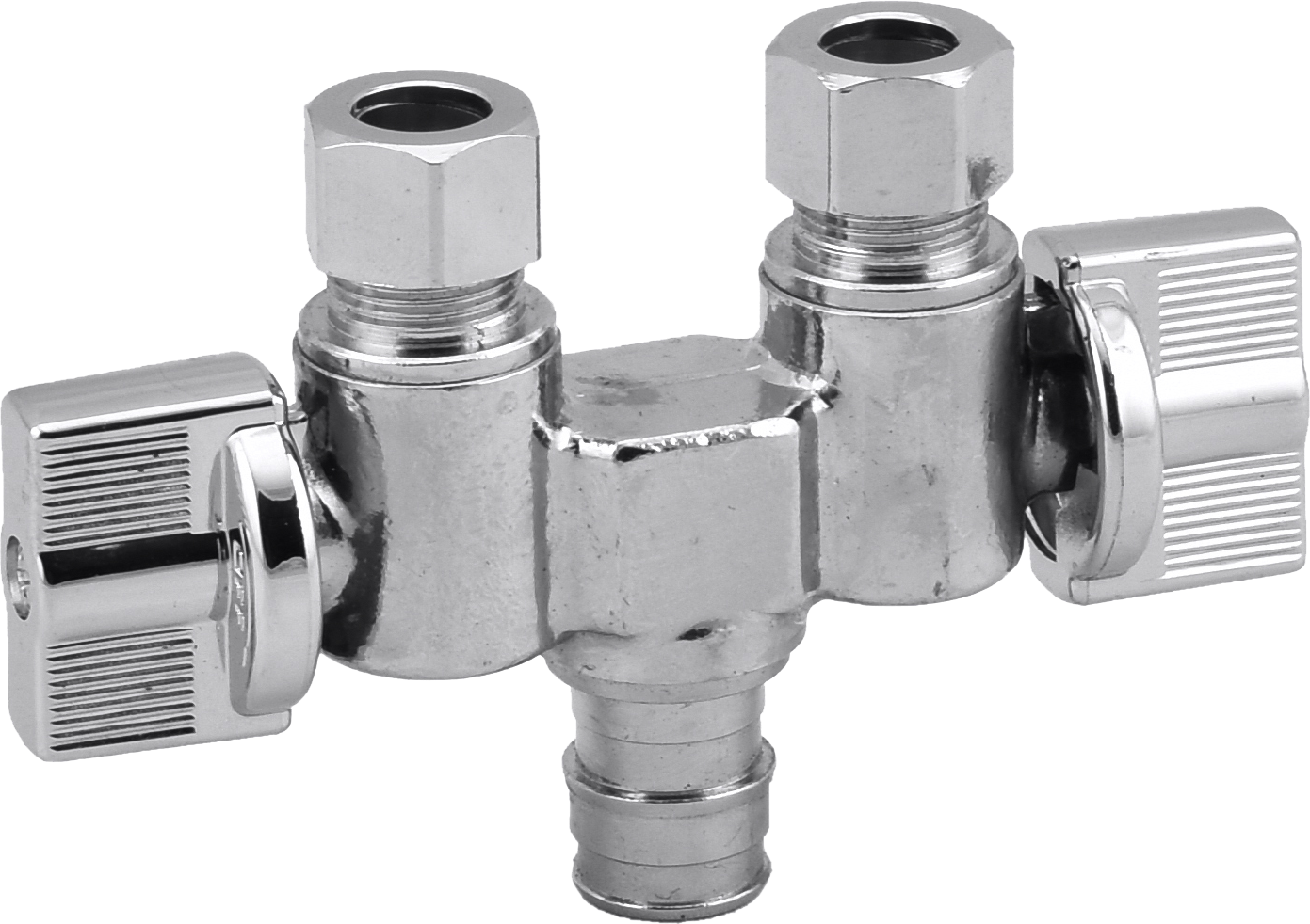
Figure 1 — Brass valve and supply stop range used at leak-critical joints in residential and commercial water lines. Image: LONGDA BRASS VALVE.
Problem Definition: The Three Leak Paths in a Brass Valve Installation
Field failures in brass valve installations are not random. They cluster into three mechanical paths, and each one has a different root cause and a different countermeasure.
Path 1 — Connection leakage at the joint
Connection leakage is the most common and the most preventable. It has four recurring causes: a thread-form mismatch between valve and pipe, insufficient or excessive tightening, contamination trapped in the joint, and a connection method that does not match the piping system. NPT is a tapered thread governed by ASME B1.20.1, where the seal is formed by thread interference plus sealant. BSP is a parallel thread governed by ISO 228-1, where pressure tightness is not made on the thread itself. Joining an NPT valve to a BSP port, or the reverse, produces a joint that cannot be made reliable by adding more tape or more torque.
Path 2 — Stem leakage across the pressure boundary
The stem is the only part that moves while the valve is under pressure, which makes its sealing system the second failure path. Stem leakage typically develops from side loading during handle operation, from O-ring hardening in hot or chemically aggressive water, and from retention hardware that no longer holds the stem squarely. When the stem is not positively retained, a pressure surge can push it out of the body — a failure that is both a leak and a safety event.
Path 3 — Thread damage and body porosity
The third path is often invisible at handover. Cross-threading on the first turn cuts a new, shallow thread that weeps under pressure. Separately, a cast body or fitting with internal porosity can pass a short factory test and still weep through the wall months later, once thermal cycling and water hammer have worked on the void. This is why thread quality and body density belong in the purchase specification, not only in the installation checklist.
Industry Background: Leak Prevention Is Now a Specification Issue
Two structural changes have moved leak control from the installer's toolbox into the buyer's specification sheet.
Market scale and product mix. The global brass valves market was valued at USD 14.8 billion in 2025 and is projected to reach USD 24.1 billion by 2034, growing at a CAGR of 5.6% from 2026 to 2034 (Dataintelo, 2025). Ball valves held the largest product-type share at 38.4% in 2025, and Asia Pacific accounted for 41.2% of revenue in the same year, with North America at approximately 26.1%. A category of this size, dominated by quarter-turn products, means the sealing details of ball valves and supply stops determine the leak rate of entire installation programmes.
The lead-free transition. Lead-free brass alloys are now the mandatory standard for potable water applications in the United States under the Safe Drinking Water Act (US EPA). The alloys used to meet that requirement — Eco-Brass C69300, CW724R, Lead-Free Brass C4650, CW511L, Low Lead Brass CW509L and CW510L, and DZR CW602N — behave differently from conventional CW617N under machining and forging. Thread quality, dimensional stability and body density therefore depend more heavily on process control than they did a decade ago, and porosity that was tolerable in a cast conventional alloy becomes a leak path in a harder lead-free alloy.
Standards now do the enforcing. A compliant submittal package for a potable water project typically references NSF/ANSI 372 for lead content (wetted surface lead ≤ 0.25%), NSF/ANSI 61 for health effects, and cUPC listing against ASME A112.18.1 / CSA B125.1 for supply stops. Threads are referenced to ASME B1.20.1 for NPT and ISO 228-1 for BSP; PEX expansion joints to ASTM F1960; copper alloy ball valves for drinking water in the EU to EN 13828:2003; brass gas valves to EN 331:2015; and copper alloy castings to ASTM B584. Each of these standards addresses a specific leak mechanism, which is why a submittal review is also a leak review.
Detailed Solution: How the Right Valve Construction Removes Each Leak Path
The 8081 ball valve: blow-out-proof stem and PTFE seats
The 8081 ball valve addresses the stem path directly. Its blow-out-proof stem design keeps the stem mechanically captured in the body, so a pressure surge cannot displace it even if the retaining hardware degrades. Behind that retention sit two independent sealing layers: a PTFE seat and double O-ring stem sealing, combined with a quarter-turn ball core and a chrome-plated anti-corrosion finish. The practical effect is that the stem seal is not a single point of failure — the O-rings handle dynamic sealing while the PTFE seat handles static shut-off, and PTFE's low friction keeps operating torque low so the user is less likely to force the handle and side-load the stem.
The quarter-turn action matters for leak prevention over the life of the installation. A ball core that turns 90 degrees wears the stem packing far less than a multi-turn mechanism that rotates repeatedly across the same sealing surface, which is why ball valves and quarter-turn supply stops dominate fixture-level shut-off.
15111 fittings and the T-22017A gate valve: hot-forged bodies eliminate porosity
Hot forging is the countermeasure to Path 3. Forging works the metal under heat and pressure, closing internal voids instead of leaving them in place as casting can. The 15111 fittings and the T-22017A gate valve are produced with hot-forged construction specifically to deliver a dense pressure boundary, so the wall of the body and fitting cannot weep through a porosity pocket. For a gate valve used for isolation duty, where the body stays full of water under static head for long periods, a dense forged wall is the difference between a component that holds for its service life and one that shows a stain on the ceiling in year two.
Body material follows the application. Standard bodies are hot-forged normal brass CW617N, while potable water contact requires lead-free brass with wetted surface lead ≤ 0.25% in line with NSF/ANSI 372 and the US Safe Drinking Water Act. Seats are PTFE and O-rings are NBR or EPDM, selected for the temperature and chemistry of the line.
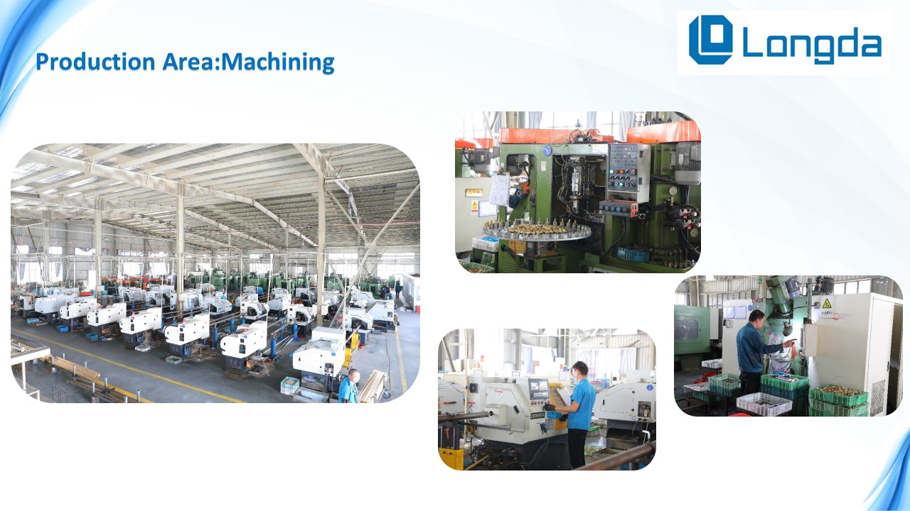
Figure 2 — In-house forging and machining control body density and thread geometry, the two variables behind porosity leaks and thread-damage leaks. Image: LONGDA BRASS VALVE.
Thread standard control: NPT, BSP and gauge inspection
Threads are the cheapest place to prevent a leak and the most expensive place to fix one. Two controls close this path. First, thread form must be fixed at order stage: NPT to ASME B1.20.1 for North American systems, BSP to ISO 228-1 for European and many export markets, and never mixed within one joint. Second, thread geometry must be verified by gauge rather than by eye — thread gauge inspection is carried out on every lot, so a worn die or a drifting tool cannot ship.
Verification before shipment
Construction only counts if it is verified. Every unit is 100% air pressure tested before shipment, a lead-free material test report is available for potable water orders, and the lead-free range carries cUPC listing plus NSF/ANSI 61 and NSF/ANSI 372 certification. Coverage extends to a 12-month quality warranty with free replacement. The manufacturing base behind these controls is a 30,000 m² facility with roughly 200 employees, an annual output of 7,500 tons, and more than 360 sets of processing and testing equipment, including spectral analysis instruments, pressure testing sets, roundness measuring equipment and salt-spray test boxes. The company is IAPMO and ALS certified, and serves plumbing, heating, HVAC, refrigeration and power station applications.
Matching the connection method to the piping system
Leak risk is also a function of connection choice. The brass valve range supports threaded (NPT and BSP), compression, FIP, sweat, press, push-fit, CPVC and PEX connections, including F1807 PEX and F1960 expansion. PEX-A expansion joints made to ASTM F1960 are commonly specified for potable water branch lines and floor heating, where working pressure runs up to 100 psi (0.7 MPa) and temperature up to 180°F (82°C); the cold expansion process forms a permanent joint without reducing the pipe inner diameter, which keeps velocity and erosion low.
Step-by-Step Breakdown: Eight Installation Steps That Remove the Leak Risk
Use Cases: Where Each Leak Path Dominates
Residential fixture supply. Behind sinks, toilets and washing machines, working pressure typically runs 40–80 psi (0.28–0.55 MPa) at 4°C–60°C in confined, humid space. The dominant risk is connection leakage from a mis-matched thread or an over-torqued compression nut, and the second risk is stem leakage because the stop is operated repeatedly during maintenance.
Commercial and municipal water supply. Working pressure up to 200 psi (1.4 MPa) and temperatures from -10°C to 110°C, including wet and corrosive environments and high-frequency operation. Full-port on/off control with minimal pressure drop is the requirement, and project specifications for USA and Canada commonly call for lead-free brass with wetted surface lead ≤ 0.25%, NSF 61 / NSF 372 certification, cUPC listing, ASME B16.34 / MSS SP-110 compliance, NPT or BSP threads and 100% pressure testing.
PEX repiping and branch lines. Whole-house repiping and potable branch lines run up to 100 psi (0.7 MPa) at up to 180°F (82°C) in long-term continuous service. ASTM F1960 expansion joints are the leak-critical interface here, and the 8081 ball valve with a quarter-turn lever gives a full-port shut-off without reducing the pipe bore.
Heating and HVAC. Central heating, chilled water and underfloor heating systems operate at up to 232 psi (1.6 MPa) and 4°C–90°C in continuous duty. Manual balancing valves are specified for precise flow distribution between circuits, and EU projects reference PED 2014/68/EU and EN 215 for radiator balancing valves, with Kv values and pressure drop curves supplied.
Gas installations. Brass gas valves for EU projects must comply with EN 331:2015, which addresses the safety requirements specific to gas service — a different leak consequence class from water, and a different verification route.
Comparison Table: Leak Modes, Countermeasures and What to Verify
| Leak mode | Typical root cause | Design / installation countermeasure | What to verify in the submittal |
|---|---|---|---|
| Connection leakage | NPT / BSP mismatch; under- or over-tightening; debris in the joint | Fix thread form at order stage; hand-tighten then wrench-tighten without side load | Thread standard stated (ASME B1.20.1 for NPT, ISO 228-1 for BSP); thread gauge inspection record per lot |
| Stem leakage | O-ring hardening; side load through the body; stem not positively retained | Blow-out-proof stem with double O-ring sealing and PTFE seat; hold the body with a second wrench | Stem design and seal arrangement; 100% air pressure test before shipment |
| Body / fitting porosity | Internal voids in the pressure boundary, revealed by thermal cycling | Hot-forged bodies and fittings (15111 fittings, T-22017A gate valve) instead of porous castings | Body construction route; copper alloy casting reference ASTM B584 where castings are used |
| Thread damage | Cross-threading; worn dies; shallow thread form | Hand-start every joint; gauge-verified threads on every lot | Dimensional report plus thread gauge inspection record |
| Material non-compliance | Lead-free alloy substitution; unverified alloy grade | Specify lead-free brass to NSF/ANSI 372 and NSF/ANSI 61 | Lead-free material test report; cUPC listing; alloy grade (C69300, C4650, CW511L, CW509L, CW510L, CW602N) |
| PEX joint failure | Incorrect expansion depth or hold time | Make up per ASTM F1960 cold expansion procedure with marked insertion depth | Compatibility statement for ASTM F1960 / F1807 and the pipe standard ASTM F876 / F877 |
Table 1 — Each leak path mapped to its countermeasure and the document that proves it. Sources: LONGDA BRASS VALVE product data; ASME B1.20.1; ISO 228-1; ASTM B584; ASTM F1960.
| Comparison point (equal quality level) | LONGDA BRASS VALVE supply stop line | Average supply stop factories |
|---|---|---|
| Standard model coverage | 50+ standard models across sizes, connections and finishes | Typically 10–20 models |
| Price position at equal quality | 5%–10% price advantage | Reference baseline |
| Quality record | 0 quality complaints in the past 3 years | Higher complaint rates reported in comparison |
| On-time delivery | Above 98% | Stable but less controllable |
| Sample lead time | 5–7 days | Longer for new specification development |
| Quotation response | Within 24 hours | Varies |
Table 2 — Supplier-level comparison for leak-critical supply stop and brass valve programmes, based on LONGDA BRASS VALVE first-party data.

Figure 3 — Specification coverage and price position at an equal quality level, the two variables that determine total leak-related cost. Image: LONGDA BRASS VALVE.
Frequently Asked Questions
Which standards must a leak-resistant brass valve meet for US and Canadian potable water systems?
A potable water brass valve for the US and Canadian market should demonstrate wetted surface lead content of ≤ 0.25% per NSF/ANSI 372 and the US Safe Drinking Water Act, including California AB1953; conformance to NSF/ANSI 61 for health effects; cUPC listing against the applicable performance standard, such as ASME A112.18.1 / CSA B125.1 for supply stops; NPT threads to ASME B1.20.1; and ASTM F1960 for PEX-A expansion connections. In the EU, copper alloy ball valves for drinking water are referenced to EN 13828:2003 and brass gas valves to EN 331:2015. LONGDA BRASS VALVE supplies lead-free versions with cUPC, NSF/ANSI 61 and NSF/ANSI 372 certification, and the company holds IAPMO and ALS certification.
What design features actually prevent stem leakage?
Stem leakage is prevented by three features working together: a blow-out-proof stem that stays mechanically captured in the body under pressure, double O-ring stem sealing that provides two independent dynamic barriers, and PTFE seats combined with a quarter-turn ball core and a chrome-plated anti-corrosion finish. Verification matters as much as design — every unit is 100% air pressure tested before shipment, and thread gauge inspection is performed on every lot. A 12-month quality warranty with free replacement supports the assembly in service.
How do leak-resistant brass valves compare on price at an equal quality level?
At the same quality level, the LONGDA BRASS VALVE supply stop line offers a 5%–10% price advantage over comparable factories, together with 50+ standard models covering sizes, connections and finishes, against the 10–20 models typical of average factories. The larger specification coverage and the zero-complaint record over the past three years reduce the cost of returns, claim handling and safety stock, which is where most of the real cost of a leaking valve sits.
Can I evaluate samples before committing to a production order?
Yes. Sample lead time for the supply stop and brass valve lines is 5–7 days, and quotation response is within 24 hours, which also shortens new specification development when a project requires a non-standard size, connection or finish. Samples allow the thread form, stem seal and finish to be checked against the project's submittal requirements before volume production begins.
What lead time and delivery reliability should a distributor plan for?
The on-time delivery rate for this product line is above 98%, which keeps lead times stable and controllable for long-term supply programmes, repeat distributor replenishment and retail chain restocking. Combined with the 12-month quality warranty with free replacement, this is the basis for planning safety stock around a predictable delivery window rather than a buffer against missed shipments.
Conclusion: Design Out the Leak, Then Install It Correctly
Leaks in brass valve installations are not an unavoidable cost of doing business. They follow three predictable paths — the connection, the stem, and the thread or body wall — and each path has a defined countermeasure. On the design side, a blow-out-proof stem with double O-ring sealing and PTFE seats, as used in the 8081 ball valve, removes the stem path; hot-forged bodies and fittings, as used in the 15111 fittings and the T-22017A gate valve, remove the porosity path; and gauge-verified threads to ASME B1.20.1 or ISO 228-1 remove the thread path. On the installation side, matching the thread form, applying approved sealant correctly, tightening without side load, making up press and PEX joints to ASTM F1960, and pressure testing the assembly close the remaining gaps.
For buyers, the practical rule is to treat leak prevention as a purchasing requirement rather than an installation instruction. Ask for the thread standard, the thread gauge inspection record, the 100% pressure test record and the lead-free material test report before the order is placed — those four documents predict field performance far better than a torque specification alone.
Next step: LONGDA BRASS VALVE supplies brass ball valves, gate valves, supply stops, check valves, fittings and PEX valves for residential and commercial water, heating and gas systems, with lead-free options certified to cUPC, NSF/ANSI 61 and NSF/ANSI 372. Download the full product catalogue to check sizes, connections and finishes for your project, or send your specification for a quotation within 24 hours.
📄 Catalogue: Longda Global Product Catalogue (PDF)
🌐 Website: www.ld-valve.com
✉️ Email: sales@ld-valve.com | WhatsApp / Tel: +86 13506869135 (Libby Xiao)
📍 Xuangang Industry Zone, Lupu Town, Yuhuan County, Zhejiang Province, China
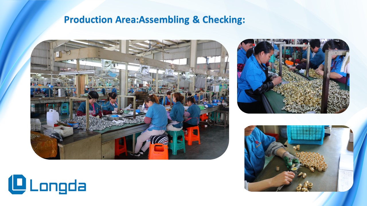
Figure 4 — Production area at the Yuhuan facility, where hot-forged brass valve and fitting bodies are machined, gauged and pressure tested. Image: LONGDA BRASS VALVE.
Have Questions or Need More Details?
Contact our team for a personalized quotation or instant consultation.
Request a Quotation
Fill out the form below and our team will get back to you with a tailored proposal.
WhatsApp Direct Chat
Prefer to chat in real-time? Message us on WhatsApp for instant assistance & quick answers.
- Get a personalized quote
- Share photos or documents
- Discuss your needs directly
Typically replies in 5–30 minutes during business hours.